Your match
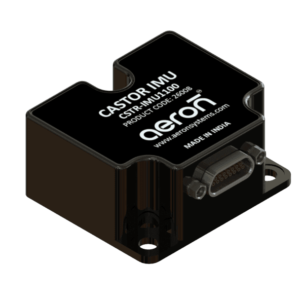
Castor IMU 1100
Miniature Tactical 6DOF IMU with RS422 Interface
- InterfaceRS422, External Trigger Input, Time of Validity (TOV), Auxiliary Input
- Accelerometer range±10 g
- Inclinometer range±1.7 g
This is the model on show
Show this modelInertial Measurement Unit
Miniature 6DOF IMU (OEM PCB Mounted) with SPI Interface
CSTR-IMU1640
Two short questions on what it measures and how it connects, and the model that fits.
Compare all our IMUsWhat must it measure?
How will it connect?
Your match: Castor IMU 1100
Your match
Miniature Tactical 6DOF IMU with RS422 Interface
This is the model on show
Show this modelYour match
Miniature 6DOF IMU (OEM PCB Mounted) with SPI Interface
This is the model on show
Show this modelYour match
Tactical Grade 3-Axis Gyro Module
This is the model on show
Show this modelThe Castor series CSTR-IMU1100 is a high-end tactical class inertial measurement unit consisting of high-performance tri-axial accelerometer, tri-axial gyroscope, and tri-axial inclinometer sensors based on the latest MEMS technology, delivering control-grade inertial measurement data over an RS422 interface.
Its rugged and modular design, with output available over an RS422 interface, makes the IMU 1100 suitable for integration with control computers and other application hardware in guidance, navigation, and control systems, robotics and gimbal control, unmanned ground vehicles, and flight control systems.
Raw accelerometer, gyroscope, and inclinometer signals are calibrated, temperature-compensated, and digitally filtered in real time before being delivered as control-grade inertial data over RS422.
In
Out
Excellent 0.7 deg/hr (typically) in-run bias instability, thermal compensation, and good short-term turn-on to turn-on repeatability.
IMU1100 features configurable filters with programmable taps optimising the IMU for best performance.
Factory calibrated for misalignment, offsets, and scale factor errors and temperature compensated.
IMU1100 is designed for shock survival up to 1500g making it suitable for high dynamics applications.
RS422 Interface, external trigger, diagnostics, and data ready options for integrated communication with user controller.
Offers update rates of up to 2000Hz and configurable bandwidth as per customer application requirements.
Low supply voltage requirement making it possible to power up the IMU with low voltage battery systems.
Low noise and highly stable accelerometer and gyroscope sensors for high performance sensor data.
Wide operating temperature range and temperature compensation of sensors for useful performance across operating range.
| Range | ±480 °/s |
|---|---|
| Bias Instability | 0.7 °/hr (typ.) — 0.5 to 1.2 °/hrAt 25°C |
| Angle Random Walk (ARW) | 0.13 °/√hr (typ.) — 0.09 to 0.2262 Hz LPF, at 25°C |
| Bias Repeatability | ±100 °/hr |
| Bandwidth | 262 Hz, −3dB |
| Noise Density | 0.001 °/s / √Hz |
| Resolution | 24 bits |
| Scale Factor Accuracy | < 500 ppm1σ, at 25°C |
| Non-Linearity | < 40 ppm1σ, full scale ±480°/s |
| Range | ±10 g |
|---|---|
| Bias Instability | 0.020 mg (typ.) — 0.016 to 0.024 mgAt 25°C |
| Velocity Random Walk (VRW) | 0.018 m/s/√hr (typ.) — 0.018 to 0.028262 Hz LPF, at 25°C |
| Bias Repeatability | ±1.5 mg |
| Bandwidth | 262 Hz, −3dB |
| Noise Density | 0.0001 m/s² / √Hz |
| Resolution | 24 bits |
| Dimensions | 38.6 (L) × 44.8 (W) × 21.5 (H) mm |
|---|---|
| Weight | 72 ± 3 gm |
| Connector (Device) | Micro-D Pin: MDA215SFSP4 |
| Connector (Mating) | Micro-D Socket: MDA215P4L150S |
| Fixation Bolts | M4 metric |
| Recommended Torque | 3 Nm |
| Range | ±1.7 g |
|---|---|
| Bias Instability | 0.028 mg (typ.) — 0.021 to 0.035 mgAt 25°C |
| Velocity Random Walk (VRW) | 0.026 m/s/√hr (typ.) — 0.024 to 0.032262 Hz LPF, at 25°C |
| Bias Repeatability | ±1.2 mg |
| Noise Density | 0.0001 m/s² / √Hz |
| Input Voltage | 4.5 to 5.5 VDC |
|---|---|
| Power Consumption | < 1.3 W |
| Update Rate | Up to 2000 Hz |
| AUX (Full Scale) | ±2.5 V |
| Diagnostics | Continuous onboard temperature, voltage & sensor health monitoring |
| Operating Temperature | −40°C to +85°C |
|---|---|
| Storage Temperature | −55°C to +90°C |
| Mechanical Shock | 1500 g / 0.5 ms half-sineMIL-STD-883F Method 2002.4, Test Condition B |
| Ingress Protection | IP65 |
| Hardware | RS422, External Trigger Input, Time of Validity (TOV), Auxiliary Input |
|---|---|
| Software | Binary |
| Baud Rate | 374,400 to 1,843,200 bit/s |
| Time to Transmit after Power ON | 0.6 sec |
|---|---|
| Time to Transmit after Reset | 1.5 sec |
| Time to First Valid Data | 0.6 sec |
 Guidance, Navigation and Control
 Drone Navigation and Control
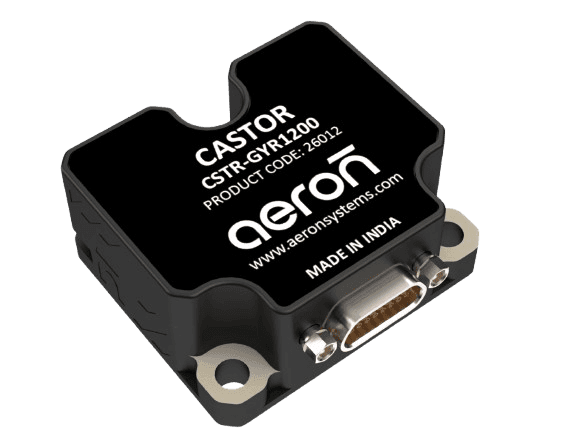
CSTR-GYR1200 is a high-end tactical class gyro module built around a high-performance triaxial MEMS gyroscope. A high-speed onboard processor runs digital signal processing algorithms to deliver control-grade inertial measurement data over a standard RS422 interface, running off a single +5V supply.
The sensing elements of each axis are factory-calibrated for bias and misalignment, and compensated for temperature effects across the full −40°C to +85°C operating range. Its rugged, modular design and 1500 g shock qualification make GYR1200 well suited for integration with control computers and other application hardware in guidance, navigation, and control systems.
Triaxial gyroscope signals are calibrated and temperature-compensated in real time by Castor's onboard digital signal processor to deliver stable, control-grade angular-rate data.
In
Out
0.6°/hr in-run bias instability, thermal compensation, and good turn-on to turn-on repeatability.
GYR1200 is qualified up to 1500 g mechanical shock, making it suitable for high-shock platforms.
Built-in capabilities that allow the device to monitor its own health and functionality, alerting users to potential issues in real time.
The sensor's output drift (bias) remains minimal over time, leading to more stable and accurate measurements.
Compact size, low weight, high performance, with calibration, compensation, and ruggedized mounting options.
Used for precise timing, deterministic operation, data integrity, and synchronization verification.
| Bias Instability | 0.6 °/hrAt 25°C |
|---|---|
| Angle Random Walk (ARW) | 0.1 °/√hr262 Hz LPF, at 25°C |
| Range | ±480 °/s |
| Bias Range | −250 to +250 °/hr (typ. +2 °/hr) |
| Bandwidth | 262 Hz−3dB (262 Hz LPF) |
| Noise Density | 0.002 °/s/√Hz |
| Resolution | 24 bits |
| Scale Factor Accuracy | ≤ 500 ppmAt 25°C, for ±450°/s |
| Non-Linearity | 10 ppm (±250°/s) · 20 ppm (±400°/s) |
| Bias Repeatability | 3 °/hr |
| Misalignment | 1 mrad |
| Bias Error Over Temperature | 50 °/hr |
| Bias Error Over Temperature Gradient | 70 °/hr |
| Dimensions | 37.6 (L) × 43.8 (W) × 19 (H) mm (± 0.3 mm) |
|---|---|
| Weight | 60 g (± 4 g) |
| Connector | Micro-D Pin MDA215SFSP4 (Device) · Micro-D Socket MDA215P4L150S (Mating) |
| Fixation Bolts | M4 metric |
| Recommended Torque | 3 Nm |
| Input Voltage | 4.5 to 5.5 V DC |
|---|---|
| Power Consumption | 1.2 WTolerance: ±0.5 W |
| Diagnostics | Continuous onboard temperature, voltage, and sensor health monitoring |
| Update Rate | Up to 2000 Hz |
| Logic Level — High | ≥ 2.6 V DC |
|---|---|
| Logic Level — Low | ≤ 1.6 V DC |
| Minimum Hold Time for Reset | 1 µs |
| Pull-Up Resistor | 100 kΩ |
| Operating Temperature | −40°C to +85°C |
|---|---|
| Storage Temperature | −55°C to +90°C |
| Mechanical Shock | 1500 g / 0.5 ms half-sineMIL-STD-883F Method 2002.4, Test Condition B |
| Ingress Protection | IP65 |
| Hardware | RS422, External Trigger Input, Time of Validity (TOV) |
|---|---|
| Software | Binary |
| Baud Rate | 374400 to 1843200 bits/s |
| Time to Transmit After Power ON | 0.27 sec |
|---|---|
| Time to Transmit After Reset | 0.26 sec |
| Time to First Valid Data | 0.275 sec |
| Input Resistance (Termination ON) | 120 ΩTolerance ±5% |
|---|---|
| Input Resistance (Termination OFF) | 300 kΩ |
 Unmanned Ground Vehicle
 Drone Navigation and Control
 Guidance, Navigation and Control
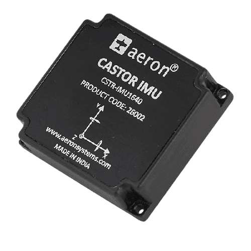
The Castor series IMU1640 is a high-end tactical-class inertial measurement unit consisting of a high-performance triaxial MEMS accelerometer and triaxial gyroscope built on the latest MEMS technology. A high-speed onboard processor runs superior digital signal processing algorithms to deliver control-grade inertial measurement data over a digital SPI interface.
The sensing elements of each axis are factory-calibrated for bias and misalignment and are temperature-compensated to remain usable across the full operating range. The IMU is designed to be mounted firmly on the customer's own PCB, and its rugged, modular design makes it suitable for integration with control computers and other application hardware where size is a constraint.
Raw accelerometer and gyroscope signals are calibrated, temperature-compensated, and digitally filtered in real time before being delivered over the SPI interface.
In
Out
Excellent 1°/hr in-run bias instability, thermal compensation, and good turn-on to turn-on repeatability.
IMU1640 features configurable FIR filters with programmable taps optimising the IMU for best performance.
Factory calibrated for temperature, misalignment, offsets, and scale factor errors.
Offers update rates of up to 4250 Hz and configurable bandwidth as per customer application requirements.
IMU1640 is designed for shock survival up to 1500g, making it suitable for high dynamics applications.
Low supply voltage requirement (3 to 3.6V DC) making it possible to power up the IMU with low voltage battery systems.
Low noise and highly stable accelerometer and gyroscope sensors for high performance sensor data.
Wide operating temperature range and temperature compensation of sensors for useful performance across operating range.
Digital SPI interface, digital inputs and outputs, diagnostics and data-ready options for integrated communication with the user controller.
| Range | ±480 °/s |
|---|---|
| Bias Instability ² | 1 °/hr (Typ.)0.6–1.6 °/hr, at 25°C |
| Angle Random Walk (ARW) | 0.14 °/√hr (Typ.)0.11–0.2 °/√hr, 262 Hz LPF, at 25°C |
| Bias Repeatability ⁵ | ±250 °/hr |
| Bandwidth | 400 Hz−3dB (262 Hz LPF) |
| Resolution | 32 bits |
| Scale Factor Accuracy | < 500 ppm1σ, at 25°C |
| Non-Linearity ⁴ | < 40 ppm1σ, for full scale ±480°/s |
| Range | ±16 g (±40 g Overrange) |
|---|---|
| Bias Instability ¹ | 0.019 mg (Typ.)0.015–0.020 mg, at 25°C |
| Bias Repeatability ⁵ | ±1.5 mg |
| Velocity Random Walk (VRW) | 0.017 m/s/√hr (Typ.)0.015–0.06 m/s/√hr, 262 Hz LPF, at 25°C |
| Bandwidth | 400 Hz−3dB (262 Hz LPF) |
| Noise Density | 0.0005 m/s²/√HzWith filter |
| Resolution | 32 bits |
| Dimensions | 47 (L) × 44 (W) × 14 (H) mm |
|---|---|
| Weight | 57 ± 3 g |
| Connector (Device) | MW-12-03-G-D-118-118 |
| Connector (Mating) | MLE-112-01-G-DV-A-P |
| Fixation Bolts | M2 metric |
| Recommended Torque | 0.35 Nm |
| Input Voltage | 3 to 3.6 V DC |
|---|---|
| Power Consumption | < 1 W |
| Update Rate | Up to 4250 Hz |
| Diagnostics | Continuous onboard temperature, voltage & sensor health monitoring |
| Operating Temperature ⁶ | −40°C to +71°C |
|---|---|
| Storage Temperature | −55°C to +85°C |
| Mechanical Shock ³ | 1500 g / 0.5 ms half-sineAs per MIL-STD-883F, Method 2002.4, Test Condition B |
| Ingress Protection | IP65 |
| Hardware | SPI, 4 × Digital I/Os |
|---|---|
| Software | Binary |
| SPI Clock Speed | 15 Mbps |
| Time to Transmit After Power On | 0.9 sec |
|---|---|
| Time to First Valid Data | 0.9 sec |
 Unmanned Ground Vehicle
 UAV Control and Stabilization
 Attitude Control and Stabilization
IMU 1100, GYR 1200, IMU 1640 side by side.
| IMU 1100Accel + Gyro + Inclinometer · RS422 | GYR 1200Gyroscope-Only Module · RS422 | IMU 1640Accel + Gyro · OEM SPI | |
|---|---|---|---|
| Sensor Suite | |||
| Sensors | Accelerometer, Gyroscope, Inclinometer | Gyroscope only | Accelerometer, Gyroscope |
| Gyro Bias Instability | 0.7°/hr (typ.) | 0.6°/hr (typ.) (stronger) | 1°/hr (typ.) |
| Accelerometer Bias Instability | 0.02 mg (typ.) | — | 0.019 mg (typ.) |
| Update Rate | Up to 2000 Hz | Up to 2000 Hz | Up to 4250 Hz (stronger) |
| Communication & Interface | |||
| Interface | RS422 | RS422 | SPI (15 Mbps) |
| Data Format | Binary | Binary | Binary |
| Mounting | Standalone module | Standalone module | OEM PCB-mount (board-to-board connector) |
| Electrical & Power | |||
| Input Voltage | 4.5 to 5.5 V DC | 4.5 to 5.5 V DC | 3 to 3.6 V DC |
| Power Consumption | < 1.3 W | 1.2 W | < 1 W (stronger) |
| Mechanical & Environmental | |||
| Dimensions | 38.6 × 44.8 × 21.5 mm | 37.6 × 43.8 × 19 mm | 47 × 44 × 14 mm |
| Weight | 72 ± 3 g | 60 ± 4 g | 57 ± 3 g (stronger) |
| Mechanical Shock | 1500 g / 0.5 ms half-sine | 1500 g / 0.5 ms half-sine | 1500 g / 0.5 ms half-sine |
| Operating Temperature | −40°C to +85°C | −40°C to +85°C | −40°C to +71°C |
| Ingress Protection | IP65 | IP65 | IP65 |
Common questions about the .
CSTR-IMU1100 can be interfaced on RS422.
CSTR-IMU1100 has a dynamic measurement range of 400 deg./s and up to 40g
It combines tri-axial accelerometers, gyroscopes, and magnetometers.
It offers typical bias instability of approximately 1°/hr.
Common questions about the .
The GYR1200 is designed for applications such as drone navigation and control, robotics, unmanned ground vehicles (UGVs), aerospace guidance systems, and defence-grade motion control systems.
The unit communicates through an RS422 interface, allowing reliable high-speed communication with control computers, autopilots, and embedded systems.
The Castor GYR1200 offers a typical in-run bias instability of 0.6°/hr, delivering stable and accurate angular rate measurements for tactical navigation applications.
Common questions about the .
The CSTR-IMU1640 is suitable for UAV flight control, robotics, unmanned ground vehicles, motion stabilisation systems, aerospace guidance, and high-dynamics defence applications.
The CSTR-IMU1640 communicates over a high-speed SPI interface, enabling seamless integration with embedded controllers, autopilots, and onboard processing systems
Yes, the CSTR-IMU1640 is designed as an OEM PCB-mounted IMU and can be integrated directly onto the customer’s control board using a board-to-board connector.
Other products from Robotics & Industrial, sized by their real dimensions.
Ask for a price on Castor IMU, or talk to one of our engineers about your application.
Sales
Products, quotes and demos
Technical support
Help with an installed product
Careers
Jobs and applications
India
Plot No. 7, Lane No. 5, Laxman Nagar, Balewadi
Pune, Maharashtra 411045, India
Vivan Kohli Industrial Park, Shed No. 5, Gat No. 446
Old Pune-Mumbai Highway, Naigaon, Kanhe Phata, Talegaon
Pune, Maharashtra 412106, India
First Floor, Building No. 11, Sai Anugraha
Jeevan Bhima Nagar Main Road
Bengaluru, Karnataka 560075, India
Door No. 52-1/4-8D, Plot No. 9, 5th Cross Road
Veterinary Colony
Vijayawada, Andhra Pradesh 520008, India
International
Saif Executive Office # P8-17-02
Sharjah Airport International Free Zone Authority
PO Box 8000, Sharjah, U.A.E.